

DaliControl e64 Pro
Order no. 4101-145-02
Dimensions (L x W x H) 90 / 71 / 58 mm
The DaliControl e64 Pro offers convenient switching and dimming functions, control of light colour and emergency lighting as well as operating hours recording and a complex error analysis of the connected devices. The device supports DALI standard DT-8 as well as emergency lights according to DT-1 and the connection of DALI-2 input devices for presence, brightness and pushbutton information. In addition, the DaliControl e64 Pro offers a convenient web interface to perform quick configuration and control tasks using the web browser. The device supports KNX Data Secure.
Emergency lighting:
Yes
Additional interface:
IP-interface
DALI-2 certified:
Multi Master
Connection mode:
KNX Secure
News

New functions and features for the DaliControl e64 Pro - V2.1.0 now available
With version 2.1.0, the Multi Master Controller e64 Pro gets constant light control. The complete package includes not only the firmware V2.1.0, but also the ETS application V2.1 and the DCA V2.1.0.0.
DaliControl e64 Pro - V2.1.0
New functions and features for the DaliControl e64 Pro - V2.0.2 now available
The Multi Master Controller e64Pro gets a complete software update with version 2.0.2. Not only the firmware of the devices has been revised, but also the ETS application and the DCA.
DaliComtrol e64 Pro - V2.0.0 DaliControl e64 Pro - V2.0.2
Product Info
The IPAS DALI Gateway DaliControl e64 Pro is a multi-master application controller for controlling electronic ballasts with DALI interface via the KNX installation bus. It supports ballasts according to EN 62386-102 ed1 (DALI1), devices according to EN 62386-102 ed2 (DALI2), as well as DALI2 motion sensors and light sensors according to EN 62386-303 and EN 62386-304.
The device transforms switching and dimming commands from the connected KNX system into corresponding DALI telegrams, or status and event information from the DALI bus into KNX telegrams.
The DaliControl e64 Pro has a DALI output which can control up to 64 ECGs. In addition, up to 8 DALI2 motion detectors or light sensors can be connected. Multi-master operation according to EN 62386-103 ed2 is permitted.
The required power supply for the connected ECGs and motion sensors is provided directly by the device. Additional DALI power supply is not required. When using sensors supplied via the DALI bus, it must be ensured that the current consumption of all connected DALI devices does not exceed the guaranteed value.
The device is available in a 4 DU wide DIN rail housing for direct installation in an electrical distribution board. The bus connection is made via a standard bus connector. Mains and DALI lines are connected via screw terminals on the device. Ethernet is connected via an RJ45 socket.
Per gateway the ECGs can be controlled in 16 groups. In addition to the group control the DaliControl e64 Pro also allows individual control of up to 64 ECGs.
As well as the control of all standard operating devices, the DaliControl e64 Pro enables the operation of single battery emergency lights (EN 62386-202) and supports emergency lighting systems with central battery.
A maximum of 8 motion detectors with light sensors can also be controlled.
Functions

Operating modes
Normal mode: Groups and ECGs can be switched without restrictions. Permanent mode: After the ETS download groups in permanent mode are continuously switched on.
Normal mode: Groups and ECGs can be switched without restrictions. Permanent mode: After the ETS download groups in permanent mode are continuously switched on.

Night mode: The mode can be changed from normal mode to night mode via an object. In night mode, groups switch off after a period of time or they change into permanent mode.

Panic mode: All groups that are enabled for panic mode are switched to a pre-set value and can no longer be switched off.

Staircase function
This function makes it possible to switch off groups with a time delay. The times are adjustable. The function can be locked via an object and in this state, the groups are in normal mode.
This function makes it possible to switch off groups with a time delay. The times are adjustable. The function can be locked via an object and in this state, the groups are in normal mode.

Operation hours counter
This function counts the switch-on times of groups and/or ECGs. The counter reading can be used as threshold value for an alarm notification, for example when the service life has been reached.
This function counts the switch-on times of groups and/or ECGs. The counter reading can be used as threshold value for an alarm notification, for example when the service life has been reached.

Error analysis
Error rates are calculated based on the number of lamp and ECG errors and the number of all connected lamps. Threshold values for errors and error rates can be defined. An alarm is triggered when these are reached.
Error rates are calculated based on the number of lamp and ECG errors and the number of all connected lamps. Threshold values for errors and error rates can be defined. An alarm is triggered when these are reached.

Scenes
With this module it is possible to program and recall up to 16 internal light scenes. A scene is invoked via a 1 Byte scene object. For DALI operating devices DT-8 the currently selected light colour or colour temperature is also saved in the scene and adjusted accordingly when the scene is invoked.
With this module it is possible to program and recall up to 16 internal light scenes. A scene is invoked via a 1 Byte scene object. For DALI operating devices DT-8 the currently selected light colour or colour temperature is also saved in the scene and adjusted accordingly when the scene is invoked.

Effect module
An effect is a sequence control of light values of different group and/or single ECGs. The individual light values can be controlled directly or dimmed via a dim value. Up to 16 independent effects can be started and stopped via a 1 Byte object. A total of 500 effect steps consisting of switch commands, value setting, colour values and delays can be distributed across 16 effects.
An effect is a sequence control of light values of different group and/or single ECGs. The individual light values can be controlled directly or dimmed via a dim value. Up to 16 independent effects can be started and stopped via a 1 Byte object. A total of 500 effect steps consisting of switch commands, value setting, colour values and delays can be distributed across 16 effects.

Energy saving function
The power supply of a group can be switched off via a KNX object when the corresponding group is switched off (standby mode). The lamp and ECG error test starts again after the power is switched back on.
The power supply of a group can be switched off via a KNX object when the corresponding group is switched off (standby mode). The lamp and ECG error test starts again after the power is switched back on.

Time control module
With the time control module, a defined light colour and, if necessary, a light value can be set automatically depending on the time and date. Up to 16 different templates are available for this purpose. A typical application is the adjustment of the colour temperature over the course of the day, which has positive effects on our well-being.
With the time control module, a defined light colour and, if necessary, a light value can be set automatically depending on the time and date. Up to 16 different templates are available for this purpose. A typical application is the adjustment of the colour temperature over the course of the day, which has positive effects on our well-being.

Quick exchange function
This function enables the easy replacement of a defective DALI ECG. One defective ECG can be replaced with a new one without DALI programming.
This function enables the easy replacement of a defective DALI ECG. One defective ECG can be replaced with a new one without DALI programming.
Technology

DT-0 groups the fluorescent lights together.

DT-1 is the specification for emergency luminaires with central battery and single battery emergency luminaires including test mode for the functions lamp, function and battery test.

DT-4 is the device type for low-voltage halogen lamps.

DT-6 describes the control of LED lamps.

The methods for color control RGBW, HSV, Tunable White and room coordinates x/y have been defined by the DiiA in the new device type 8 (DT8). In practice, DALI DT-8 reduces the number of light control channels required to a minimum and thus reduces the individual channel price. The simple installation method, cost-effective light channels and complex possibilities to adjust an individual light based on color, brightness and intensity are among the most important arguments that speak for DALI in lighting technology.

DALI technology
The cross-functional DALI Bus (DALI = Digital Addressable Lighting Interface) is a system used to control electronic ballasts (ECGs) in lighting technology. The specifications of the DALI communication interface are defined in the international norm EN62386. Just like the KNX protocol, the DALI protocol is standardised. The Dali Association DiiA, based in the United States, is the organisation that defines and maintains DALI standards.
The cross-functional DALI Bus (DALI = Digital Addressable Lighting Interface) is a system used to control electronic ballasts (ECGs) in lighting technology. The specifications of the DALI communication interface are defined in the international norm EN62386. Just like the KNX protocol, the DALI protocol is standardised. The Dali Association DiiA, based in the United States, is the organisation that defines and maintains DALI standards.

Lights and groups
Traditionally, a DALI Master controls one DALI segment. A DALI segment consists of up to 64 DALI lights, which can be switched and dimmed in up to 16 groups.
Traditionally, a DALI Master controls one DALI segment. A DALI segment consists of up to 64 DALI lights, which can be switched and dimmed in up to 16 groups.

Single ECG control
Programmed DALI ECGs are accessible via the short address in a DALI segment and can thus be controlled in the DaliControl gateway from the KNX (except color control via DT-8).
Programmed DALI ECGs are accessible via the short address in a DALI segment and can thus be controlled in the DaliControl gateway from the KNX (except color control via DT-8).

2 DALI segments in a gateway
Powerful controllers allow the integration of 2 DALI segments in one device. This means that a total of 2 x 64 DALI lights, which are assigned to a total of 2x16 groups, can be controlled.
Powerful controllers allow the integration of 2 DALI segments in one device. This means that a total of 2 x 64 DALI lights, which are assigned to a total of 2x16 groups, can be controlled.

DALI installation
The DALI installation is simple. The wiring usually consists of a 5-core cable (typically 5x1.5 m2 NYM) that connects all 64 lights in parallel. 3 cores, L, N and PE, are used for the energy supply and the remaining 2 cores are used for the DALI bus.
The DALI installation is simple. The wiring usually consists of a 5-core cable (typically 5x1.5 m2 NYM) that connects all 64 lights in parallel. 3 cores, L, N and PE, are used for the energy supply and the remaining 2 cores are used for the DALI bus.

DALI broadcast
According to DALI protocol, a Broadcast command is a central switch command that is independent of group assignments. DaliControl devices use DALI broadcast commands for switching on and off, value setting, color values (RGB or HSV) and color temperature via KNX objects. Broadcast does not require DALI assignment.
According to DALI protocol, a Broadcast command is a central switch command that is independent of group assignments. DaliControl devices use DALI broadcast commands for switching on and off, value setting, color values (RGB or HSV) and color temperature via KNX objects. Broadcast does not require DALI assignment.

Lamps/ECG error
A major advantage of DALI technology over KNX lighting control is the reporting and acknowledgment of lamp and ECG errors by the DALI system. This information is of vital importance for operational safety and lighting management.
A major advantage of DALI technology over KNX lighting control is the reporting and acknowledgment of lamp and ECG errors by the DALI system. This information is of vital importance for operational safety and lighting management.

ETS programming
IIPAS DaliControl interfaces are ETS5 and ETS6 compatible. The programming of DALI lights is assigned via the Device Control App (DCA). The DCA is integrated into the ETS once and includes all functions for programming the DALI components in the associated DALI segment.
IIPAS DaliControl interfaces are ETS5 and ETS6 compatible. The programming of DALI lights is assigned via the Device Control App (DCA). The DCA is integrated into the ETS once and includes all functions for programming the DALI components in the associated DALI segment.

Installation systems
In installation systems in which DALI lights are controlled via the KNX installation, the DALI KNX interface constitutes the DALI Master. Like the KNX Bus, the DALI Bus is a two-wire bus.
In installation systems in which DALI lights are controlled via the KNX installation, the DALI KNX interface constitutes the DALI Master. Like the KNX Bus, the DALI Bus is a two-wire bus.

IP interface
The integrated web server is accessible via the IP interface. In conjunction with the CBSE Dali Management Tool (DMT), the IP interface can be used to exchange system data (operating hours, test results, error information, etc.).
The integrated web server is accessible via the IP interface. In conjunction with the CBSE Dali Management Tool (DMT), the IP interface can be used to exchange system data (operating hours, test results, error information, etc.).

Web server
DALI new and post-installation, scenes, effects and timer sequences configurable via the integrated web server, retrieving status information and switching groups and ECGs.
DALI new and post-installation, scenes, effects and timer sequences configurable via the integrated web server, retrieving status information and switching groups and ECGs.

Data backup
The ETS configuration is backed up within the project in the ETS. The DALI configuration can be backed up as an XML file and imported and programmed again via the ETS.
The ETS configuration is backed up within the project in the ETS. The DALI configuration can be backed up as an XML file and imported and programmed again via the ETS.
Colour Controls

RGBWAF colour channels
With this type of colour control, the colour perception is based on the additive mixing of the basic colours red, green and blue. In theory, the overlapping of these colours results in the colour perception “white“. In practical terms, however, it is very difficult to create a pure white tone. For this reason an additional channel for white colour can be added (RGBW). According to DALI standard IEC 62386-202, up to 6 channels (RGBWAF) can be used for colour perception in this model. In practice, three independent channels for driving the lights in red, green and blue and a channel for the color white are used. In connection with the KNX, many different colours can be easily achieved through different mixing ratios.
KNX data types for RGBW control
When using DALI DT8 lights, the color mixing takes place in the DALI ECG, so that the color information can be transmitted from the KNX side with only one object. The KNX DPT 251.600, a 6 byte data object, contains all the color information for the additive RGBW color mixing. In addition, the color range can be set via KNX 4 Bit relative dimming (DPT 3.7) or via KNX value setting (DPT 5.1).

HSV colour control
An alternative to the RGBW colour space is colour definition based on hue (H), saturation (S) and brightness values (V). This type of colour definition is often preferred for the artistic aspects of colour perception and is technically possible with only 3 objects. The colour tone is set as a value between 0° and 360°, therefore reaching all colours in the colour circle. The values for saturation and intensity (dark phase) are entered between 0 and 100%.
KNX data types for HVS control
When using DALI DT8 lights, the color mixing via HSV is also performed in the DALI ECG. The color information is transmitted from the KNX side via an angle between 0 and 360º (DPT5.3 angle). The color circle in the room is shifted via saturation (DPT 5.1) and the dimming value (also DPT 5.1). In addition, the color range can be set via standard 4Bit relative dimming (DPT 3.7) or via value setting (DPT 5.1)
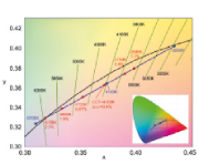
Tunable White
Over thousands of years the human organism has become accustomed to a repetitive daily cycle: At night it is dark and thus the time for our organism to relax and regenerate through sleep so that we have new energy for the following day. In the morning when the sun rises and the light has a warm tone, we get up and get ready for the day. When the sun is at its zenith around midday, the colour temperature cools down. Once the sun starts moving back towards the horizon in the afternoon, the colour temperature starts to rise again. Research has shown that the human organism functions best if it is exposed to the natural colour temperature of the specific time of day. With rapidly developing LED technology it is now possible to replicate the cyclical change of light colour temperature in the rooms in which we live and work.
The very small LED format makes it possible to integrate two different LED types, cool white and warm white, into one casing, thereby giving the impression that a lamp emits two colour temperatures. In connection with a DALI ECG those two colour temperatures are mixed dynamically. This means that almost any colour temperature can be set within a defined range between e.g. 2500 and 4500 Kelvin, simply by transmitting one information, the desired colour temperature, to the DALI ECG.
KNX data types for CW control
When using DALI DT8 lights, almost any colour temperature (CW) can be set in a defined range of, for example, 2500 to 6000 Kelvin by transmitting only one information, the desired colour temperature, to the DALI ECG. From the KNX side, this colour temperature information is transmitted via the DPT 7,600. In addition the colour temperature range and brightness can be set via the objects 4Bit relative dimming (DPT 3.7) or value setting (DPT 5.1).
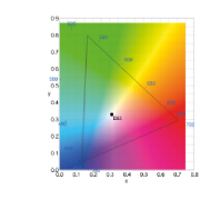
x/y – Colour Space
Another way of describing a colour is by defining a 3-dimensional colour space. In this colour space the following formula applies: x+y+z=1. A simple conversion shows that x+y =1-z. So if x and y are known, z can be easily calculated. A vector can point anywhere in the colour space and thereby define the colour. By having to define only the coordinates x and y, only two pieces of information are required to describe a colour.
The light control processes via colour temperature (Tunable White), RGBW and the coordinates x/y have all been defined by the DIIA in the new data point type 8. In practical terms, the DALI DT-8 reduces the number of required light control channels to a minimum thereby also reducing costs. Easy installation, low costs per light channel and the numerous and complex options to create customised light settings based on colour, brightness and intensity are amongst the most important reasons in favour of using DALI in lighting technology.
KKNX data types for x/y control
When using DALI DT8 lights, the room coordinates are transmitted in a value range from 0 to 65535 via the 2 byte DPT 7.1


Newsletter Registration
Informed at all times.
Register now
Questions or comments?
Contact us!
Contact form