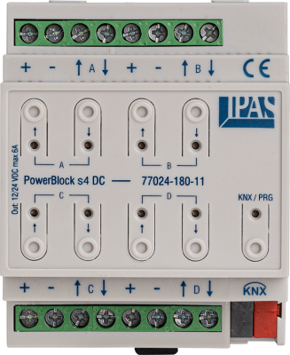
PowerBlock s4 DC
Order no. 77024-180-11
Dimensions (L x W x H) 90 / 71 / 58 mm
PowerBlock s4 DC is a blind actuator to control 4 DC blind or shutter drives. It allows the control of 24 V DC drives with load capacity of max. 6 A per contact. The ETS application program enables numerous functions (logic, scene, threshold, alarm and time modules, two-point control).
Blind/roller blind application
2 outputs each form a channel (A, B, C, D) for blind or shutter control. Thus up to 4 blind or shutter drives can be controlled with one PowerBlock s4DC. Status objects can be assigned to each channel, which signal the current position or the end position "up" and "down" (binary). Parameters define the travel time for the up and down movement and for the slat or slot opening for roller shutters. Based on these parameters, blinds and roller shutters can be controlled precisely. Blind/roller shutter channels can be integrated into the internal facade module. For facade control, additional objects are available for the corresponding facade commands up/down, position and slat position. In addition, blind/roller blind channels can be integrated into additional functions of the application module.
Installation and connection
PowerBlock s4DC is installed on the standard 35 mm top-hat rail and has a width of 4 SU. All channels are supplied with an externel 24VDC voltage. The outlets of the channel form the control for the two travel directions up/down. PowerBlock s4DC actuators are connected to the KNX bus via the standard bus connector.

This module enables the configuration of 10 scenes with a maximum of 8 objects each. 1 Bit, 1 Byte, 2 Byte and 4 Byte objects can be configured as scene objects. Objects can also disable a scene. Any events can start and save a scene. The execution of a scene can also be stopped via an object and a further object enables the restoration of a scene to its original values.

Up to 8 events can be assigned to alarms. These include analogue values such as temperature or binary status objects which, in connection with a threshold value, trigger the alarm. As a typical alarm logic, the function can be set up in such a way that alarms are acknowledged via separate objects.

Special objects count the time of closed contacts in order to determine, for example, the running time of a machine.

With just a few parameters, easy-to-use staircase functions with running time extensions and expiration warnings as well as switch-on and off delays can be configured. Timers can be activated and de-activated via additional objects.

With the logic module up to 35 logic gates can be configured. Each gate has a maximum of four inputs and one output. To select the logic function, “AND“, “OR“; “XOR“, NOT functions, gate functions, mathematical operators such as adders, subtractors, multipliers and dividers, comparators such as “greater than“, “„less than“, “equal to“ and converters for data type transformation are all available. Data point types can be configured depending on the logic function.

This module makes it possible to count incoming events. Each event can be given a factor, so that it can be counted in relation to a certain value. At the same time, a particular number of events can be assigned to a value. Each counter can be assigned threshold values which will trigger an alarm when the threshold is reached. The counter can be re-set via an object.

The application allows for the configuration of up to ten 2-point controllers. For each controller an activation object, objects for current and set value, heating and cooling mode and a binary controller output are available. In connection with the KNX data point type operating mode, individual controllers can be easily switched on and off.
Newsletter Registration
Informed at all times.
Register now
Questions or comments?
Contact us!
Contact form

